-
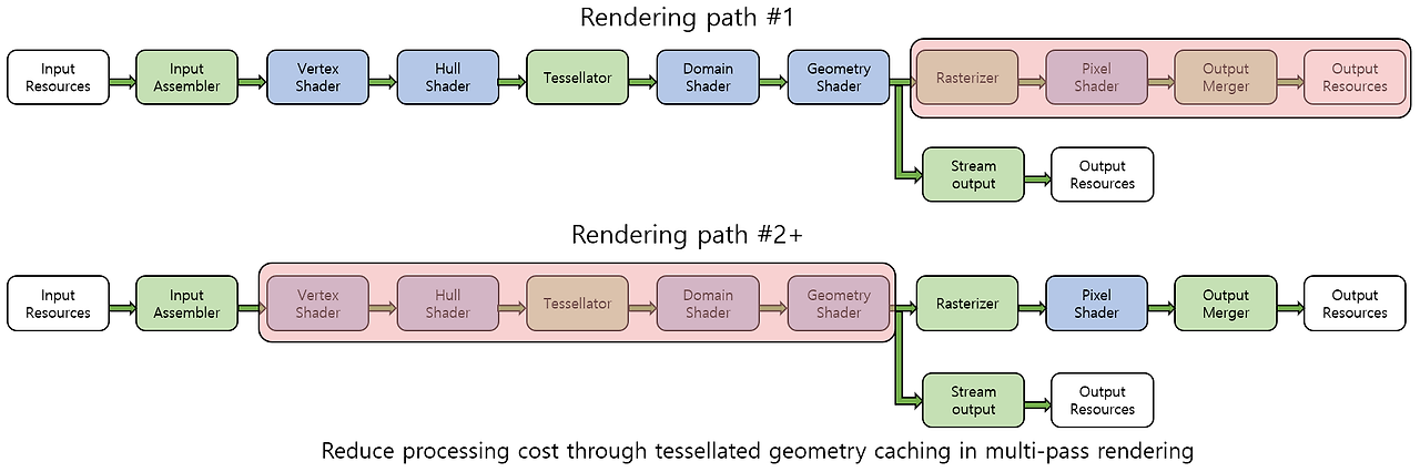
The Rendering Pipeline - After TessellationCS/게임 프로그래밍 2024. 2. 5. 01:01
Geometry Shader
Geometry Shader
- Unique abilities that are different from other stages
- Dynamically add or remove geometry to the pipeline.
- Provide geometry information to the vertex buffer through the stream output stage.
- Output a different type of primitive from the input primitive.
Input of Geometry Shader
- A completed primitive consisting of the vertices
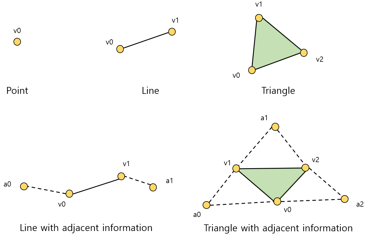
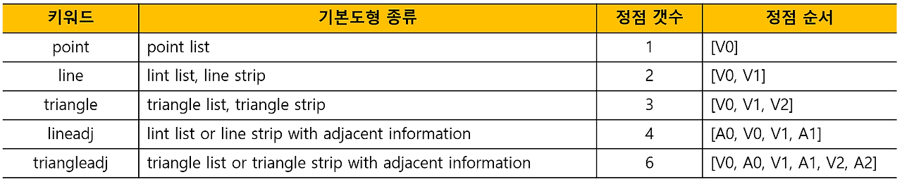
The table of completed primitives - When the tessellation stages are disabled,
- Get vertices directly from the vertex shader.
- Primitive topology is anything that input assembler can designate.
- Receive information on primitive connectivity from the input assembler.
- When the tessellation stages are activated,
- Get vertices from the domain shader.
- Primitive topology is determined by the configuration of the tessellator stage.
- Primitives with adjacent information cannot be supported.
- System value semantic
- SV_PrimitiveID : a value that uniquely idnetifies an individual primitive.
- SV_GSInstanceID : used to perform different processing for each instance of primitive.
Status Description of Geometry Shader
- Geometry shader object
- Without stream output stage : ID3D11Device::CreateGeometryShader()
- With stream output stage : ID3D11Device::CreateGeometryShaderWithStreamOutput()
- Shader program : ID3D11DeviceContext::GSSetShader()
- Constant buffer : ID3D11DeviceContext::GSSetConstantBuffers()
- Shader resource view : ID3D11DeviceContext::GSSetShaderResources()
- Sampler status object : ID3D11DeviceContext::GSSetSamplers()
- Function attribute
- maxvertexcount
- The maximum number of vertices that can be emitted into the output stream in one execution of the geometry shader.
- Used to prevent too many vertices from being output stream due to logical errors.
- instance
- Activate an instanced mechanism of a geometry shader.
- A copy (instance) of the primitive is generated as many times as specified in the function attribute.
- After that, a geometry shader program is executed for each instance.
- The maximum number of instances : 32
- maxvertexcount
Process of Geometry Shader
- The method of outputting the processing result using stream objects
- Append() : a means of sending primitive data to the output stream.
- RestartStrip() : a means for creating a geometry that is not connected to each other.
- Multi-stream object
- Up to four stream output objects can be used simultaneously in the geometry shader program.
- Used by declaring multiple stream objects in a list of function parameters.
- Each output stream operates separately from each other.
- When using a multi-stream object, all streams must be point-list streams.
- The limit of the scalar amount that can be calculated from the execution of the geometry shader is 1024.
- Manipulation of the primitive
- Possible to reduce the amount of primitives to be processed by the rasterizer.
- Geometry shader can optionally discard unnecessary primitives.
- Shadow volume : the technique of creating a shadow using the outline of the object from a light source point of view.
- Point sprite : used to make the particles of the particle system appear more plausible.
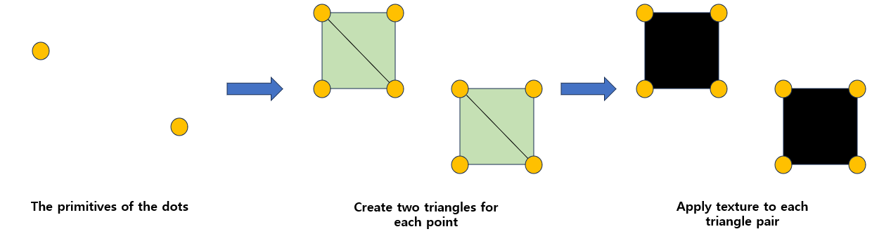
The process of generating a point sprite from a point primitive - Instancing of the geometry
- Statically specify the number of instances through instance function attribute.
- Can amplify the number appearing in the final rendering without increasing the number of the primitive.
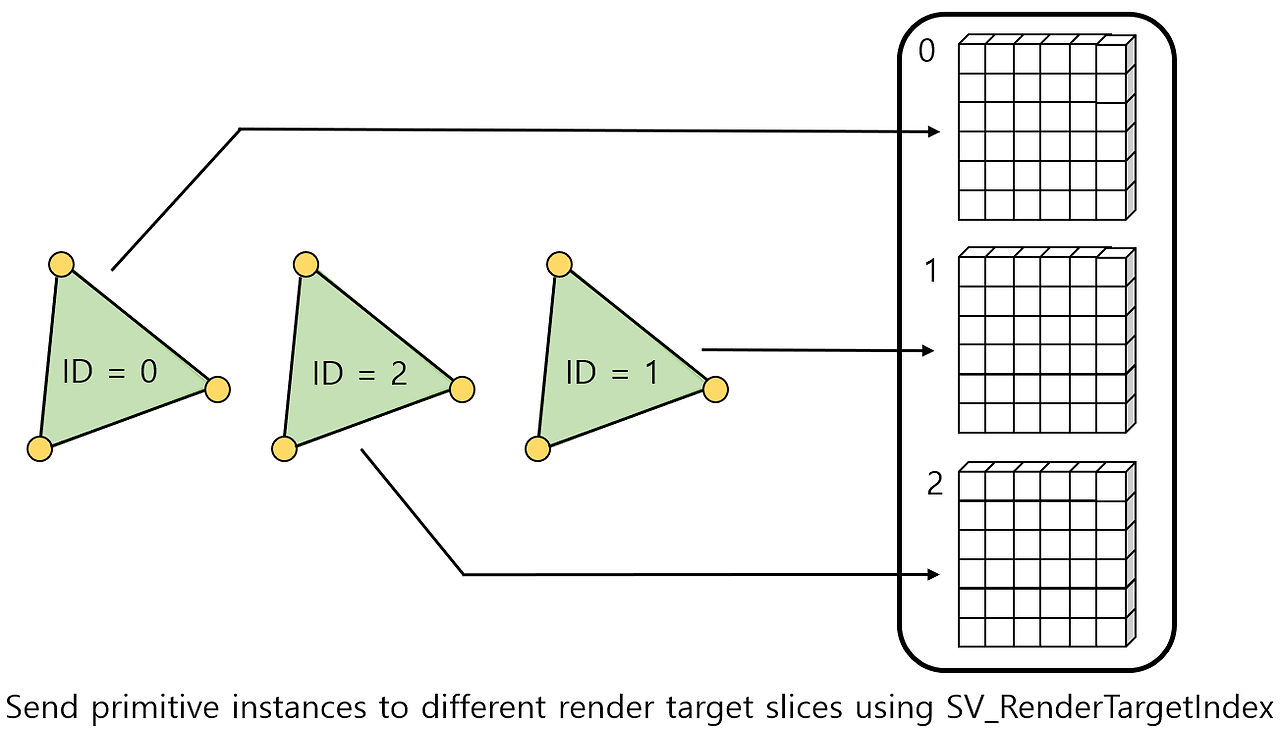
- Can render one geometry for multiple render target objects, effective when different transform matrices need to be applied to geometry for each render target object.
Output of Geometry Shader
- The vertices that must include SV_Position system value semantics, which must include the location of the culling space after projecting the vertex.
- SV_RenderTargetIndex : an unsigned integer that identifies a slice of a render target to be rendered in the current primitive.
- SV_ViewportArrayIndex : an unsigned integer that identifies a viewport to be rendered in the current primitive.
Stream Output
Stream Output
- Connect the geometry shader to the output buffer resources to which the vertex data of the geometry shader is to be recorded.
- Possible to use a total 4 output stream objects at the same time.
- The output of the stream output stage does not lead to input of any other stage of the pipeline.
Input of Stream Output
- Receive only the information delivered by the geometry shader stage through the output stream object declared in the geometry shader program.
- Different types of vertex structures can be sent for each stream.
- The limits on vertex data output as streams
- The scalar values for each vertex structure cannot exceed 128.
- The scalar values output in one shader program execution cannot exceed 1024.
Status Description of Stream Output
- The application program must link an appropriate number of buffer resources.
- Buffer resources to be connected must be generated by designating D3D11_BIND_STREAM_OUTPUT.
- The buffer resources connected to the stage are maintained in subsequent pipeline executions, so unnecessary buffers should be removed.
void ID3D11DeviceContext::SOSetTargets( // The number of buffer to bind to the device UINT NumBuffers, // The array of output buffers to bind to the device ID3D11Buffer * const *ppSOTargets, // Array of offsets to the output buffers from ppSOTargets const UINT *pOffsets );- Designate which data to send to which output slot.
struct D3D11_SO_DECLARATION_ENTRY{ // Index for identifying stream output objects used by geometry shader to send data UINT Stream; // Semantic name defined in the corresponding output attribute LPCSTR SemanticName; // Index for uniquely identifying one of several attributes with the same semantic name UINT SemanticIndex; // The starting component index (x = 0, y = 1, z = 2, w = 3) BYTE StartComponent; // How many component will be sent to the buffer from starting component BYTE ComponentCount; // Slot number of output buffer to receive stream data (0 ~ 3) BYTE OutputSlot; };- A method for generating geometry shader objects using stream output stage.
HRESULT ID3D11Device::CreateGeometryShaderWithStreamOutput(
    const void *pShaderBytecode,
    SIZE_T BytecodeLength,
// A pointer that refers to the array of the structures
    const D3D11_SO_DECLARATION_ENTRY *pSODeclaration,
// Size of the array (number of the elements)
    UINT NumEntries,
// The vertex stride and the number of vertices to be transferred to each buffer
    const UINT *pBufferStrides,
    UINT NumStrides,
// Designate the output stream that will lead to the rasterizer stage
    UINT RasterizedStream,
    ID3D11ClassLinkage *pClassLinkage,
    ID3D11GeometrySahder **ppGeometryShader
);
Process of Stream Output
- Automated rendering
- Use the recorded buffer resource as input of the input assembler stage.
- The application program must connect the buffer resource to slot 0 of the input assembler stage.
- Need to call ID3D11DeviceContext::DrawAuto()
- A vertex stream is output by the geometry shader object.
- Primitive connectivity information is determined byt the primitive type setting of the input assembler.
- Stream output as a debugging tool
- Extract information for debugging from the geometry shader stage of the pipeline.
- Used to investigate any intermediate computational value that is not included in the final rendered output.
- Two buffer resources needed
- Stream output buffer created by flagging the default : the application cannot directly access the buffer.
- Buffer designated as staging usage flag that can be read by CPU : copy the contents of the stream output buffer and read the buffer.
Output of Stream Output
- Do not lead to other pipeline stages.
- The output point of the stream output stage is a buffer resource connected to the stream output stage.
Rasterizer
Rasterizer
- Rasterization : sample geometric data at regular intervals to produce samples that can be applied to render objects.
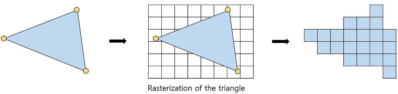
- Fragment : samples approximating the original geometry taken from rasterization.
- Culling : exclude primitives that will not contribute to the final output rendering based on the location of the culling space.
- Clipping : cut the portion outside the culling space, which will not contribute to rendering, in the primitive.
- Scissor test : to allow the application to designate a rectangular area to which rasterization is actually applied.
Input of Rasterizer
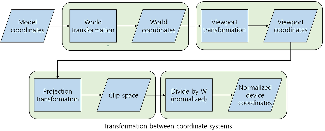
- Clip space and normalized device coordinates
- Clip space : a coordinate system after projecting the scene geometry.
- Normalized device coordinates : the coordinate divided by $W$ after projection.
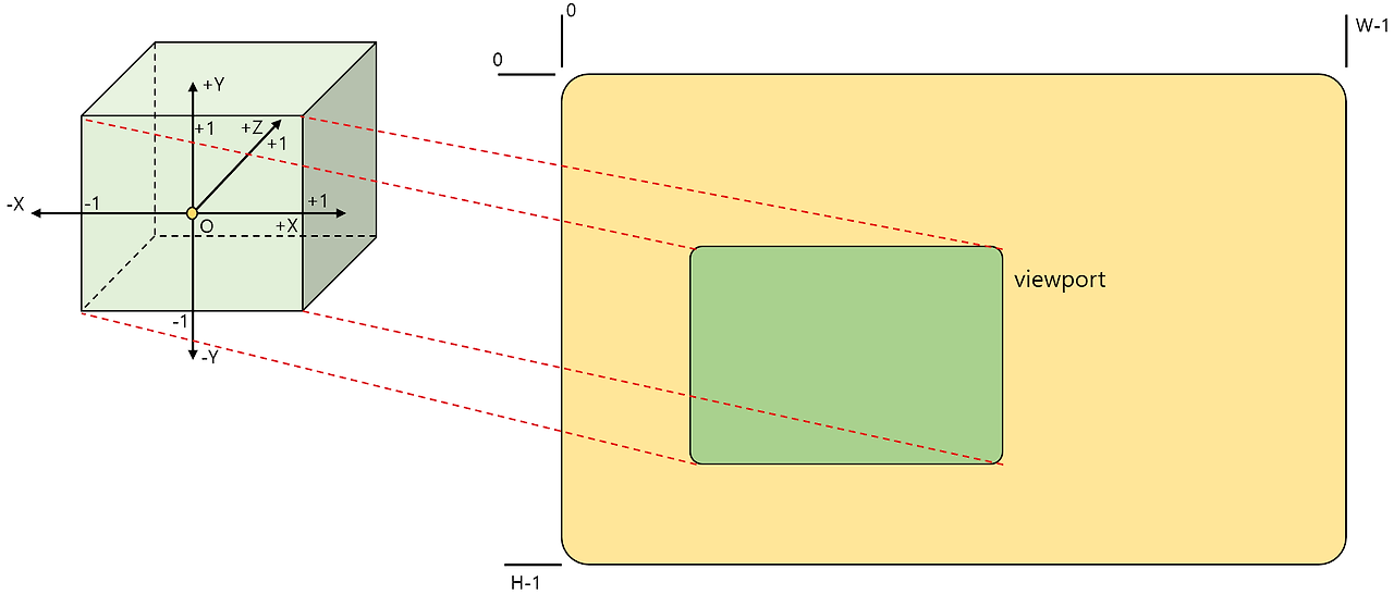
- Unit cube : a cube defining the vertex of the normalized device coordinates.
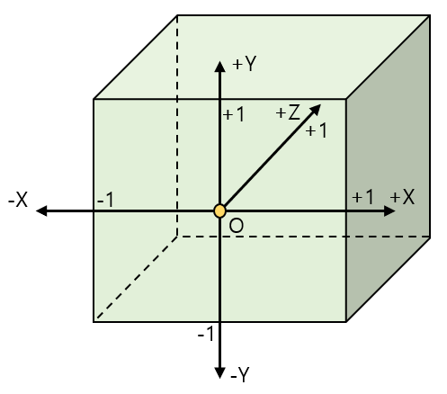
The unit cube - System value semantic of clipping distance and culling distance : SV_ClipDistance, SV_CullDistance
- Viewport array index; SV_ViewportArrayIndex : an unsigned integer that identifies the viewport defining structure to be used when rastering the primitive.
- Render target array index; SV_RenderTargetArrayIndex : an unsigned integer identifying a slice to record rendering results among texture slices of a render target array.
Status Description of Rasterizer
- Rasterizer state object
struct D3D11_RASTERIZER_DESC { // Determine the fill mode to use when rendering (solid fill or wireframe) D3D11_FILL_MODE FillMode; // Indicate triangles facing the specified direction are not drawn D3D11_CULL_MODE CullMode; // Determine if a triangle is front- or back-facing BOOL FrontCounterClockwise; // Depth value added to a given pixel INT DepthBias; // Maximum depth bias of a pixel FLOAT DepthBiasClamp; // Scalar on a given pixel’s slope FLOAT SlopeScaledDepthBias; // Enable clipping based on distance BOOL DepthClipEnable; // Enable scissor-rectangle culling BOOL ScissorEnable; // Specify whether to use the quadrilateral or alpha line anti-aliasing on MSAA render targets BOOL MultisampleEnable; // Specify whether to enable line antialiasing BOOL AntialiasedLineEnable; }; HRESULT CreateRasterizerState( // Pointer to a rasterizer state desciption const D3D11_RASTERIZER_DESC *pRasterizerDesc, // Address of a pointer to the rasterizer state object created ID3D11RasterizerState **ppRasterizerState );- Formula corresponding to the method of applying depth bias
- When the depth buffer connect to the pipeline is unorm, or not connected at all
$$Bias \ = \ (float)DepthBias \ * \ r \ + \ SlopeScaledDepthBias \ * \ MaxDepthSlope$$ - When the floating point depth buffer is connected to the pipeline
$$Bias \ = \ (float)DepthBias \ * \ 2(exponent(maximum\ z\ of\ the \ primitive) \ - \ r)$$$$+\ SlopeScaledDepthBias \ *\ MaxDepthSlope$$
- When the depth buffer connect to the pipeline is unorm, or not connected at all
- Viewport status
- Define a rectangular area used to map normalized device coordinates based on a unit cube to pixel positions based on a render target coordinate system.
- ID3D11DeviceContext::RSSetViewports : the method of setting viewports on the pipeline.
- Viewports not set in the pipeline are automatically released.
struct D3D11_VIEWPORT{ FLOAT TopLeftX; FLOAT TopLeftY; FLOAT Width; FLOAT Height; FLOAT MinDepth; FLOAT MaxDepth; };- Scissor rectangle
- Designate an area where fragments are allowed to be generated among the render targets.
- ID3D11DeviceContext::RSSetScissorRects() : the method of binding an array of scissor rectangles on the pipeline.
- Scissor rectangles not set in the pipeline are automatically released.
Process of Rasterizer

- Culling : exclude the entire primitive that will not contribute to the final rendering result.
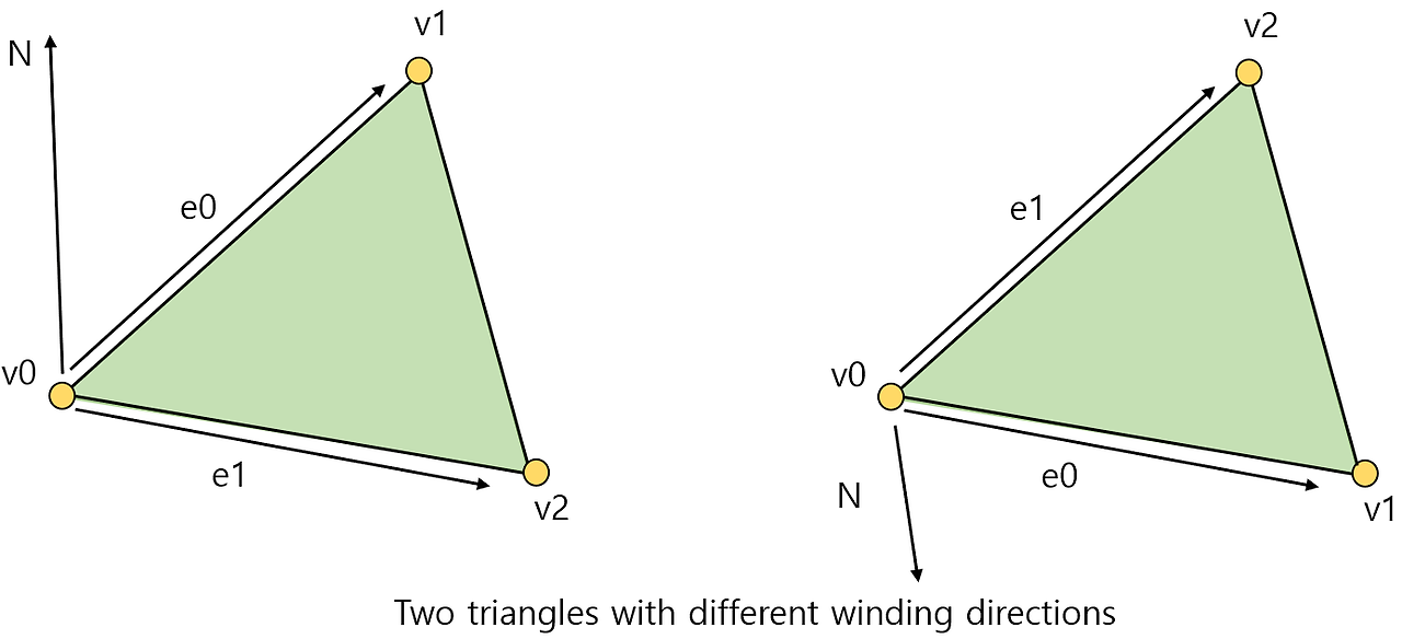
- Back face culling
- Exclude the side facing backward. (The side away from the viewpoint)
- Apply only to triangles in primitive.
- Whether the triangle is front or rear is determined by the 'winding' of the triangular vertices that the rasterizer receives.
- Primitive culling
- Exclude primitives that are completely out of the unit cube within normalized device coordinates.
- If all of the vertices of a primitive are outside of one clipping plane, it is certain that the primitive is outside the unit cube of clipping space.
- Primitive clipping
- Determine whether a given primitive is completely or partially contained in a unit cube.
- Completely contained : pass to the next task without performing a clipping operation.
- Partially contained : cut out the primitive and discard the outer part.

The example of primitive clipping - Homogenous divde : divide the projected point into $W$ components. $[X\ / \ W, \ Y \ / \ W, \ Z \ / \ W, \ 1]$
- Viewport transformation
- Mapping a primitive of normalized device coordinates to a screen space pixel coordinates.
$$ X\ : \ [TopLeftX, \ TopLeftX \ + \ Width], \ Y \ : \ [TopLeftY, \ TopLeftY \ + \ Height]$$ - How the application selects a viewport to be applied to the current rendering pass
- Include SV_ViewportArrayIndex : select an element in the viewport array using the system value as an index.
- Not include SV_ViewportArrayIndex : connect only one viewport and the application no longer manipulates the viewport.
- Mapping a primitive of normalized device coordinates to a screen space pixel coordinates.
Process of viewport transformation - Actual rasterization processing
- Convert a given primitive into discrete sample data approximated within the render object.
- Fragment generation : determine the pixels that the primitive will cover from the currently given render target.
- Regard a render object as a grid of pixels.
- Determine pixels covered by a given primitive among pixels of the grid.
- Scissor test
- Set scissor test by connecting a scissors rectangular arry to the rasterizer stage.
- Compare the $X$ and $Y$ components of the fragment with the scissors rectangle.
- Exclude the fragment outside the rectangle, that the fragment does not
- Attribute interpolation : the rasterizer interpolates each of the input attributes of the input geometry vertex
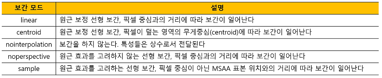
Available interpolation modes - Multi-sampling considerations : optional MSAA processing capability; apply MSAA by selecting the part that requires anti-aliasing
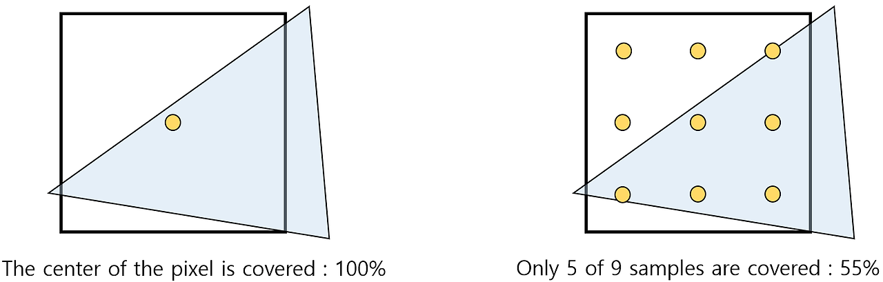
Difference between MSAA activation and deactivation Output of Rasterizer
- Generation of the fragment
- The output should be reduced as much as possible because of the overall data "amplification".
- More efficient to perform calculations before numerous fragments are generated.
- Fragment data
- Depth value interpolated for each fragment, which used for depth determination of the output merger stage.
- SV_Position : the position of the fragments
Pixel Shader
Pixel Shader
- Determine the appearance of a fragment based on the information provided through the attributes of the fragment and various resources.
- Execute a designated pixel shader program for each fragment to process the fragments.
- Any direct communication between individual fragment processes is impossible, since each pixel shader execution operates independently.
Input of Pixel Shader
- Attribute interpolation
- Essential information involved in the interpolation process of attributes
- Attribute values of the data to be interpolated.
- The location where interpolation occurs.
- Interpolation mode : specific types of interpolation techniques.
- Linear mode : apply linear interpolation considering perspective effects.
- After dividing each vertex attribute by the vertex depth, interpolation is performed.
- Extract the original attributes using the reciprocal of the interpolated $W$.
- Noperspective mode : interpolate attributes based only on the 2D position on the render object.
- Nointerpolation mode : the attribute values of the first vertex of the primitive apply to all fragments of the primitive.
- Centroid mode : the centroid of the partial sample positions covered by the primitive, not the center position of the pixel, is used as the input of the interpolation function.
- Sample mode : interpolation occurs at each sample point.
- Essential information involved in the interpolation process of attributes
- MSAA and pixel shader
- Execution by sample
- Make the pixel shader perform once per subpixel, not once per pixel.
- Including SV_SampleIndex among input signatures activates execution by sample.
- Partial sample coverage
- An unsigned interger value corresponding to each partial sample of the current pixel.
- Including SV_Coverage among input signatures activates partial sample coverage.
- Execution by sample
- Fragment position
- The original location
- The 4-component location of the fragment is transferred to the pixel shader through SV_Position
- In general, $X$ and $Y$ components indicate the location of a fragment in 2D render object.
- If centroid is specified, the value of centroid used in the interpolation is transmitted.
- SV_Position includes the depth value (0 ~ 1) generated by the rasterizer.
- Destination of the fragment : select the render target slice on which the fragments of the given primitive will be recorded based on SV_RenderTargetArrayIndex
- The original location
- Direction of the primitive
- SV_IsFrontFace : indicate the direction of the primitive
- true : generated from the front primitive / false : generated from the back primitive
- Always true in primitives of dots and lines because there is no concept of direction.
Status Description of Pixel Shader
- Shader program : ID3D11DeviceContext::PSSetShader()
- Constant buffer : ID3D11DeviceContext::PSSetConstantBuffers()
- Shader resource view : ID3D11DeviceContext::PSSetShaderResources()
- Sampler status object : ID3D11DeviceContext::PSSetSamplers()
- Unordered access view
- Capable of performing 'scatter writing'
- Scatter writing : programmatically determine where to store data to be written to a resource
- The place where the unordered access view is actually connected is not the pixel shader stage, but the output merger stage.
- Early depth-stencil determination
- earlydepthstencil function attribute
- Depth-stencil determination is performed before the pixel shader is executed.
- Pre-remove fragments that are certain to fail the depth or stencil determination.
Process of Pixel Shader
- The execution of the pixel shader
- Call a pixel shader once for every given fragment.
- Calculate the output color of the fragment.
- Deliver the output color to the output merger stage
- Simultaneously perform multiple different pixel shader calls using parallel processing units of the GPU, because of the one-to-one model and data sharing restrictions between threads.
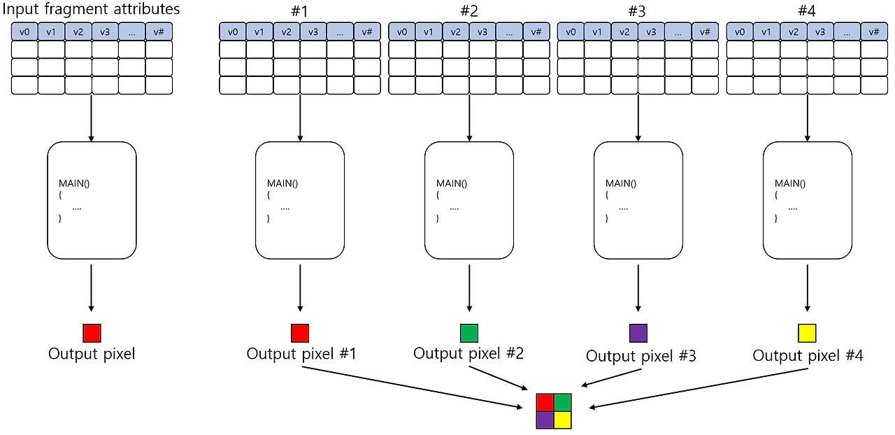
Parallel processing for multiple pixel shader calls - Multiple render targets; MRT : used when the calculation for each path are different only for the pixel shader.
MRT processing - Modify the depth value.
- Print a new depth value to SV_Depth
- If not recorded, the depth generated in the rasterizer is transferred to the output merger stage.
- Conservative depth output
- Hierarhical-Z culling; Hi-Z : determining overlapping objects in advance.
- When the pixel shader modifies the depth value, the GPU does not perform Hi-Z, because the result of Hi-Z may become inaccurate if the depth value changes after Hi-Z.
- Conservative depth output : a mean to cause Hi-Z to occur even when depth value is modified in the pixel shader.
- The pixel shader must specify not only the new depth value but also the inequality function.
- Hi-Z identifies and removes fragments that are safe to exclude based on the upper or lower limits specified by the inequality function.
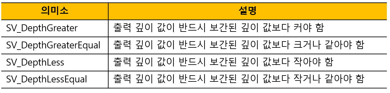
Inequality functions for Hi-Z - A simple example
// An example of calculating a color based on the material and the light float4 PSMAIN(in VS_OUTPUT input) : SV_Target { // Normalize the normal of the world space and the light vector float3 n = normalize(input.normal); float3 l = normalize(input.light); // Calculate the amount of light that has reached this fragment float4 Illumination = max(dot(n, l), 0) + 0.2f; // Get material surface color properties from the texture float4 SurfaceColor = ColorTexture.Sample(LinearSampler, input.tex); // The result of modulating the surface color to the illumination value return(SurfaceColor * input.color * Illumination); }- Utilization of unordered access view
- Ability to record values anywhere in a resource.
- Possible to generate a histogram of the rendering results while rendering the scene.
- Possible to implement a general data structure.
- Consideration of MSAA
- Extracting MSAA textures from shaders
- Load : extract partial samples from MSAA textures.
- GetDimension : provide $X$ and $Y$ sizes of textures and the number of partial samples.
- GetSamplePosition : provide the pixel coverage determination sample point corresponding to the specified partial sample.
- Alpha-to-coverage : a technique for modifying the way pixel shader outputs are recorded on render objects.
- Apply AND bitwise operation to masks generated by coverage determination and masks generated from alpha components of pixel shader output colors.
- Apply AND operation to the result and screen space dithering mask.
- As a result, a simplified fixed dithering pattern is applied to partial samples of the surface.
- Unnecessary to mix the pixel output with the content of the render target.
- Unnecessary to align the transparent surfaces according to the distance from the camera.
- Modifying MSAA behavior with pixel shader
- Execution by sample : activate execution by sample including SV_SampleIndex.
- Depth write : manipulate the depth value in the pixel shader by using SV_Depth.
- Coverage mask : pixel shader can implement its own coverage mask by changing the SV_Coverage.
- Extracting MSAA textures from shaders
Output of Pixel Shader
- SV_Target[n] : color values of the fragment.
- SV_Depth : depth values of the fragment.
- SV_DepthGreaterThan, SV_DepthLessThan
- To enable Hi-Z to operate even when recording SV_Depth in a pixel shader.
- No reason to output semantics if the pixel shader does not change the depth value directly.
- SV_Coverage
- Used to implement a customized partial sample coverage mask.
- Should be used only when using MSAA render targets are used.
Output Merger
Output Merger
- Merge the color and depth output by the pixel shader into the render object binded to the pipeline output object.
- Perform depth test that determines the visibility of pixels by depth value.
- Perform stencil test to precisely control an area in which pixels are to be recorded among render objects.
- Perform alpha blending by mixing the color value provided by the pixel shader and color value of the render object using a specific mixing function.
Input of Output Merger
- Color values calculated by the pixel shader program.
- The depth value of the fragment, which used to update contents of the depth buffer.
Status Description of Output Merger
- Depth-stencil state object
// Once created, objects can no longer be modified. struct D3D11_DEPTH_STENCIL_DESC{ // For depth test // Enable depth testing BOOL DepthEnable; // Identify a portion of the depth-stencil buffer that can be modified by depth data D3D11_DEPTH_WRITE_MASK DepthWriteMask; // A function that compares depth data against existing depth data D3D11_COMPARISON_FUNC DepthFunc; // For stencil test // Enable stencil testing BOOL StencilEnable; // Identify a portion of the depth-stencil buffer for reading stencil data UINT8 StencilReadMask; // Identify a portion of the depth-stencil buffer for writing stencil data UINT8 StencilWriteMask; // Identify how to use the results of the depth test and the stencil test for pixels whose surface normal is front / back D3D11_DEPTH_STENCILOP_DESC FrontFace; D3D11_DEPTH_STENCILOP_DESC BackFace; };- Blend state object
struct D3D11_BLEND_DESC { // Specifies whether to use alpha-to-coverage as a multisampling technique when setting a pixel to a render target BOOL AlphaToCoverageEnable; // Specifies whether to enable independent blending in simultaneous render targets // true : enable independent blending // false : only the RenderTarget[0] members are used and RenderTarget[1..7] are ignored BOOL IndependentBlendEnable; D3D11_RENDER_TARGET_BLEND_DESC RenderTarget[8]; };- Render target state object
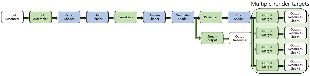
- Multiple render target; MRT
- Use multiple render target slots. (one for each render target)
- All render target are recorded simultaneously.
- The number of pixel shader calls required to record to all render targets is one per pixel.
- Render target array
- Use one render target slot.
- Only one slice is recorded at a time.
- The pixel shader program is executed as many times as the number of texture slices per pixel.
- Multiple render target; MRT
// The total number of render objects and unordered access views should not exceed 8

// Bind render target to the pipeline
void OMSetRenderTargets(
    UINT NumViews,
    ID3D11RenderTargetView **ppRenderTargetViews,
    ID3D11DepthStencilView *pDepthStencilView
);

// Bind render target with UAV
void OMSetRenderTargetAndUnorderedAccessViews(
    UINT NumViews,
    ID3D11RenderTargetView **ppRenderTargetViews,
    ID3D11DepthStencilView *pDepthStencilView,
    UINT UAVStartSlot,
    UINT NumUAVs,
    ID3D11UnorderedAccessView **ppUnorderedAccessView,
    const UINT *pUAVInitialCounts
);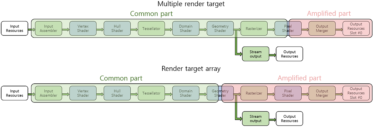
- Read-only depth-stencil view
- A write approach to the depth-stencil resource occurs in the prcess of the depth test of the output merger stage.
- Should generate a depth stencil view by specifying a 'read-only' flag that prevents the output merger stage from changing the depth stencil resource
Process of Ouptut Merger
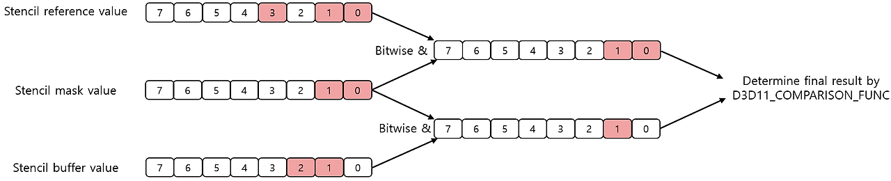
- Stencil test
- Allow the application to specify in detail the area where fragments will actually be recorded in the render object.
$$(stencil \_ ref \_ value \ \& \ stencil \_ mask) \ comp \_ op \ (stencil \_ buf \_ value \ \& \ stencil \_ mask)$$
- Allow the application to specify in detail the area where fragments will actually be recorded in the render object.
// Operations to determine how to process the stencil buffer value after passing the test enum D3D11_STENCIL_OP { D3D11_STENCIL_OP_KEEP = 1, D3D11_STENCIL_OP_ZERO = 2, D3D11_STENCIL_OP_REPLACE = 3, D3D11_STENCIL_OP_INCR_SAT = 4, D3D11_STENCIL_OP_DECR_SAT = 5, D3D11_STENCIL_OP_INVERT = 6, D3D11_STENCIL_OP_INCR = 7, D3D11_STENCIL_OP_DECR = 8 }- Depth test
- Implementation of a classical z-buffer algorithm for visibility test.
$$(the \ depth \ value \ of \ the \ fragment) \ comp\_ op \ (the \ depth \ value \ of \ the \ depth \ buffer)$$ - success : perform a blending operation / fail : discard the fragment
- Implementation of a classical z-buffer algorithm for visibility test.
- Blending operation
- Mix the two selected colors, source and destination, to calculate the final color to be recorded in the output render target.
- A complete 4-component RGBA value is created that can be recorded on the render object.
Output of Ouptut Merger
- Resources in which values can be recoded in a pipeline execution
- Render target
- Receive blending operation results, the result of applying the blending operation to the color and alpha values of.
- Unordered access view
- Directly controlled by the pixel shader stage.
- There is a slight delay in the writing process of the pixel shader.
- Depth-stencil view
- Render target
- Once a pipeline has been executed, the modified content of the resources
- Can be used in the next rendering.
- Can be used in the computation path.
- Can be directly manipulated by the CPU.
- The MSAA render object must be resolved to a non-MSAA texture after rendering is completed.
'CS > 게임 프로그래밍' 카테고리의 다른 글
The Computation Pipeline (0) 2024.03.19 The Tessellation Pipeline (0) 2024.02.12 The Rendering Pipeline - Before Tessellation (0) 2024.02.04 The Rendering Pipeline - Background (0) 2024.02.04 Direct3D 11 Resources (0) 2024.02.02 - Unique abilities that are different from other stages