-
Mesh RenderingCS/게임 프로그래밍 2024. 3. 31. 20:34
Mesh Transformations
Theory
- World coordinate - scale matrix
- Uniform scale matrix : change the size only maintaining the shape of object.
- Non-uniform scale matrix : change the size and the shape of object.
$$S \ = \ \begin{bmatrix} sx & 0 & 0 & 0 \\ 0 & sy & 0 & 0 \\ 0 & 0 & sz & 0 \\ 0 & 0 & 0 & 1 \end{bmatrix}$$
- World coordinate - rotation matrix
- No commutative property : need attention to the multiplication order.
$$R_X \ = \ \begin{bmatrix} 1 & 0 & 0 & 0 \\ 0 & cos \theta & sin \theta & 0 \\ 0 & -sin \theta & cos \theta & 0 \\ 0 & 0 & 0 & 1 \end{bmatrix}$$
$$R_Y \ = \ \begin{bmatrix} cos \theta & 0 & -sin \theta & 0 \\ 0 & 1 & 0 & 0 \\ sin \theta & 0 & cos \theta & 0 \\ 0 & 0 & 0 & 1 \end{bmatrix}$$
$$R_Z \ = \ \begin{bmatrix} cos \theta & sin \theta & 0 & 0 \\ -sin \theta & cos \theta & 0 & 0 \\ 0 & 0 & 1 & 0 \\ 0 & 0 & 0 & 1 \end{bmatrix}$$
- World coordinate - translation matrix
$$T \ = \ \begin{bmatrix} 1 & 0 & 0 & 0 \\ 0 & 1 & 0 & 0 \\ 0 & 0 & 1 & 0 \\ t_x & t_y & t_z & 1 \end{bmatrix}$$
- World coordinate - combine matrices : world matrix $W \ = \ S \ \times \ R \ \times \ T$
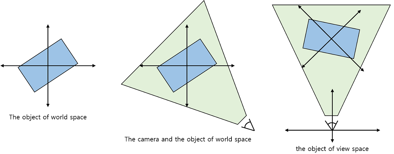
- The vertices of the model are converted from object space to world space.
- If normal vector transformation including uniform scale matrix, transformed normal vector should be normalized.
- If normal vector transformation including non-uniform scale matrix, transformed normal vector should be transformed back into a transposition matrix of the inverse matrix of the transform matrix. $$N = (W^{-1})^{T}$$
- View coordinate
- Define the location and orientation of the camera looking at the scene.$$V \ = \ T \ \times \ R_z \ \times \ R_y \ \times \ R_x \ (T \ : \ a \ negated \ position \ of \ the \ camera)$$
- Projection coordinate
- Define several other properties of the camera (FOV, aspect ratio, ...)
- Define a view frustum which determine whether objects are visible according to a given location and projection properties.
- Example of a typical projection matrix $$ P \ = \ \begin{bmatrix} xScale & 0 & 0 & 0 \\ 0 & yScale & 0 & 0 \\ 0 & 0 & z_f / (z_f - z_n) & 0 \\ 0 & 0 & - z_n \times z_f / (z_f - z_n) & 1 \end{bmatrix}$$ $$yScale \ = \ cot(fovY / 2), xScale \ = \ yScale / aspect$$
Implementation Design
- Implementation design
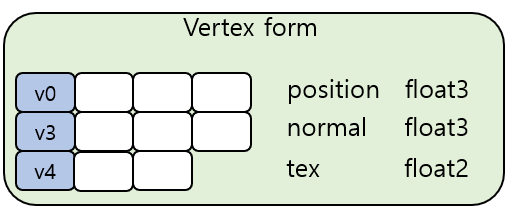
- Identify what type of data the input model is.
- Vertex positions and normal vectors
- Texture coordinates by vertex of the model
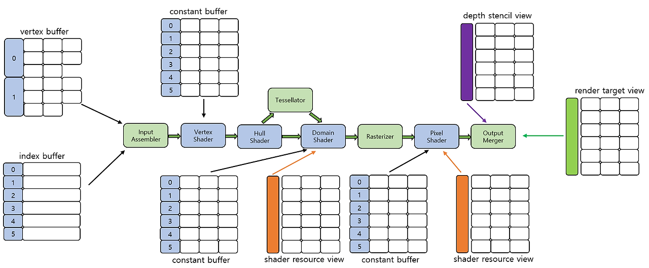
- Determine the structure of resources for model data.
- Vertex buffer : contain vertex-specific data of model
- Index buffer : contain data on the primitive
- Determine how to configure pipeline output.
- Bind a render target and a depth-stencil buffer to output merger stage.
- The render target is obtained from an swap buffer.
- Determine which part of the pipeline to use for rendering.
- Apply a transformation matrix to each vertex of the input model : calculating by vertex (vertex shader)
- Apply texture maps to the model : texture application (pixel shader)
- Identify what type of data the input model is.
Static model without animation 
Pipeline configuration for rendering static triangle mesh - Implementation example
// Resources and semantics
cbuffer StaticMeshTransforms
{
    matrix WorldMatrix;
    matrix WorldViewProjMatrix;
};

cbuffer LightParameters
{
    float3 LightPositionWS;
    float4 LightColor;
};

Texture2D ColorTexture : register(t0);
SamplerState LinearSampler : register(s0);

struct VS_INPUT
{
    float3 position : POSITION;
    float2 tex : TEXCOORDS0;
    float3 normal : NORMAL;
};

struct VS_OUTPUT
{
    float3 position : SV_Position;
    float2 tex : TEXCOORDS0;
    float3 normal : NORMAL;
    float3 light : LIGTH;
};
// Vertex shader // Convert vertices from object space to clipping space. // After one execution of the program, a converted vertex is output. VS_OUTPUT VSMAIN(in VS_INPUT input) { VS_OUTPUT output; // create a clipping space position for the rasterizer. output.position = mul(float4(input.position, 1.0f), WorldViewProjMatrix); // create a normal vector of the world space. output.normal = mul(input.normal, (float3x3)WorldMatrix); // calculate the world space position of the vertex. float3 PositionWS = mul(float4(input.position, 1.0f), WorldMaxrix).xyz; // calculate the world space light vector. output.light = LightPositionWS - PositionWS; // deliver texture coordinates. output.tex = input.tex; return output; }// Pixel shader // Determine mesh surface properties by extracting samples from texture maps. float4 PSMAIN(in VS_OUTPUT input) : SV_Target { // normalize the normal vector and light vector of world space float3 n = normalize(input.normal); float3 l = normalize(input.light); // calculate the amount of light that has reached the fragment float4 Illumination = max(dot(n, l), 0) + 0.2f; // get the color properties of the surface from the texture float4 SurfaceColor = ColorTexture.Sample(LinearSampler, input.tex); // return the result of adjusting the surface color to the light value return (SurfaceColor * Illumination); }Vertex Skinning
Theory
- Transform hierarchy
- Combination of relative transform matrices between components of a parent-child relationship.
- The child object moves from the local space defined by the parent to the world space in which the parent is placed.
- Can represent successive surfaces of parent-child relationship objects, by allocating weights that mean the influence it receives from each part at each vertex.
- Skin and bone
- Skin : the part defined by the vertices of the mesh.
- Bone : objects that make up the transform hierarchy.
- Skeleton : all bones of the model.
- Necessary to determine the number of bones to be used in the model and their connection relationship.
- Skinning-related mathematics
- Bind pose : basic direction of the bones at the time of making the model.
- The position of the vertices is defined based on the coordinate space of the entire model, not on the bone reference.
- The vertices of the model are converted from world space to bone-based space to apply the transform hierarchy matrix to the vertex.
- Cannot be calculated in advance and must be performed at the time of execution.$$B[n]_{final} \ = \ B[n]_{bind}^{-1} \ \times \ B[n]_{curr}$$
Implementation Design
- Two differences from the static mesh rendering example
- Add bone-related information to the vertex structure.
- The vertex shader program should update the arry of the bone matrices and be modified to perform bone weight interpolation.
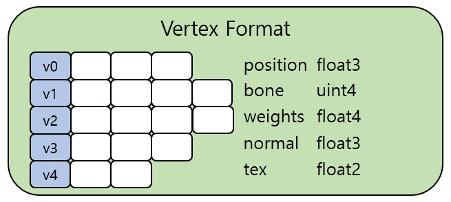
- The vertex format for vertex skinning
- bone : use to identify a particular bone matrix in a bone matrix array.
- uint4 : can use up 4 bones per vertex.
- Implementation example
// Resources and semantics
cbuffer SkinningTransforms
{
    matrix WorldMatrix;
    matrix ViewProjMatrix;
    matrix SkinMatrices[6];
    matrix SkinNormalMatrices[6];
};

cbuffer LightParameters
{
    float3 LightPositionWS;
    float4 LightColor;
};

Texture2D ColorTexture : register(t0);
SamplerState LinearSampler : register(s0);

struct VS_INPUT
{
    float3 position : POSITION;
    int4 bone : BONEIDS;
    float4 weights : BONEWEIGHTS;
    float3 normal : NORMAL;
    float2 tex : TEXCOORDS0;
};

struct VS_OUTPUT
{
    float3 position : SV_Position;
    float2 tex : TEXCOORDS0;
    float3 normal : NORMAL;
    float3 light : LIGTH;
};
// Vertex shader VS_OUTPUT VSMAIN(in VS_INPUT input) { VS_OUTPUT output; // calculate an output position of the vertex output.position = (mul(float4(input.position, 1.0f), SkinMatrices[input.bone.x]) * input.weights.x); output.position += (mul(float4(input.position, 1.0f), SkinMatrices[input.bone.y]) * input.weights.y); output.position += (mul(float4(input.position, 1.0f), SkinMatrices[input.bone.z]) * input.weights.z); output.position += (mul(float4(input.position, 1.0f), SkinMatrices[input.bone.w]) * input.weights.w); // convert the world space position into the clipping space output.position = mul(output.position, ViewPorjMatrix); // calculate a normal vector of the world space output.normal = (mul(input.normal, (float3x3)SkinNormalMatrices[input.bone.x]) * input.weights.x).xyz; output.normal += (mul(input.normal, (float3x3)SkinNormalMatrices[input.bone.y]) * input.weights.y).xyz; output.normal += (mul(input.normal, (float3x3)SkinNormalMatrices[input.bone.z]) * input.weights.z).xyz; output.normal += (mul(input.normal, (float3x3)SkinNormalMatrices[input.bone.w]) * input.weights.w).xyz; // calculate the world space light vector output.light = LightPositionWS - output.position.xyz; // deliver texture coordinates output.tex = input.tex; return output; }Vertex Skinning with Displacement Mapping
Theory
- Dynamic tessellation
- Need measurements to be used to determine how much to divide a given triangle into small pieces.
- The outline
- The most important thing is when a user recognizes an object in the world.
- Need to divided to the highest level allowed by current viewing conditions.
- The distance from the camera : the closer a triangles is to the camera, the more detailed it should be.
- LOD of displacement map to be applied to geometry : if LOD is high, the level of tessellation should be raised appropriately.

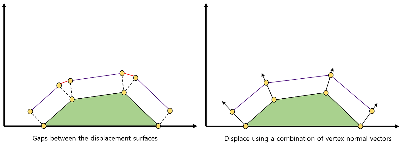
- Apply surface displacement : consider how to apply displacement to tessellated vertices.
Implementation Design
- Implementation design : use tessellation stages, by specifying control patches in the input primitive setting.
- Implementation example
// Resources and semantics
cbuffer SkinningTransforms
{
    matrix WorldMatrix;
    matrix ViewProjMatrix;
    matrix SkinMatrices[6];
    matrix SkinNormalMatrices[6];
};

cbuffer LightParameters
{
    float3 LightPositionWS;
    float4 LightColor;
};

Texture2D ColorTexture : register(t0);
Texture2D HeightTexture : register(t1);
SamplerState LinearSampler : register(s0);

struct VS_INPUT
{
    float3 position : POSITION;
    int4 bone : BONEIDS;
    float4 weights : BONEWEIGHTS;
    float3 normal : NORMAL;
    float2 tex : TEXCOORDS0;
};

struct VS_OUTPUT
{
    float3 position : SV_Position;
    float2 tex : TEXCOORDS0;
    float3 normal : NORMAL;
    float3 light : LIGTH;
};

struct HS_POINT_OUTPUT
{
    float4 position : SV_Position;
    float3 normal : NORMAL;
    float3 light : LIGHT;
    float2 tex : TEXCOORDS;
};

struct HS_PATCH_OUTPUT
{
    float Edges[3] : SV_TessFactor;
    float Inside : SV_InsideTessFactor;
};

struct DS_OUTPUT
{
    float4 position : SV_Position;
    float3 normal : NORMAL;
    float3 light : LIGHT;
    float2 tex : TEXCOORDS;
};
// Vertex shader VS_OUTPUT VSMAIN(in VS_INPUT input) { VS_OUTPUT output; // calculate an output position of the vertex output.position = (mul(float4(input.position, 1.0f), SkinMatrices[input.bone.x]) * input.weights.x); output.position += (mul(float4(input.position, 1.0f), SkinMatrices[input.bone.y]) * input.weights.y); output.position += (mul(float4(input.position, 1.0f), SkinMatrices[input.bone.z]) * input.weights.z); output.position += (mul(float4(input.position, 1.0f), SkinMatrices[input.bone.w]) * input.weights.w); // calculate a normal vector of the world space output.normal = (mul(input.normal, (float3x3)SkinNormalMatrices[input.bone.x]) * input.weights.x).xyz; output.normal += (mul(input.normal, (float3x3)SkinNormalMatrices[input.bone.y]) * input.weights.y).xyz; output.normal += (mul(input.normal, (float3x3)SkinNormalMatrices[input.bone.z]) * input.weights.z).xyz; output.normal += (mul(input.normal, (float3x3)SkinNormalMatrices[input.bone.w]) * input.weights.w).xyz; // calculate the world space light vector output.light = LightPositionWS - output.position.xyz; // deliver texture coordinates output.tex = input.tex; return output; }// Hull shader HS_PATCH_OUTPUT HSPATCH(InputPatch<VS_OUTPUT, 3> ip, uint PatchID : SV_PrimitiveID) { HS_PATCH_OUTPUT output; const float factor = 16.0f; output.Edges[0] = factor; output.Edges[1] = factor; output.Edges[2] = factor; output.Inside = factor; return output; } [domain("tri")] [partitioning("fractional_even")] [outputtopology("triangle_cw")] [outputcontrolpoints(3)] [patchconstantfunc("HSPATCH")] HS_POINT_OUTPUT HSMAIN(InputPatch<VS_OUTPUT, 3> ip, uint i : SV_OutputControlPointID, uint PatchID : SV_PrimitiveID) { HS_POINT_OUTPUT output; // calculate the output control points output.position = ip[i].position; output.normal = ip[i].normal; output.light = ip[i].light; output.tex = ip[i].tex; return output; }// Domain shader [domain("tri")] DS_OUTPUT DSMAIN(const OutputPatch<HS_POINT_OUTPUT, 3> TriPatch, float3 Coords : SV_DomainLocation, HS_PATCH_OUTPUT input) { DS_OUTPUT output; // interpolate the world space position float4 vWorldPos = Coords.x * TriPatch[0].position + Coords.y * TriPatch[1].position + Coords.z * TriPatch[2].position; // interpolate the normal vector output.normal = Coords.x * TriPatch[0].normal + Coords.y * TriPatch[1].normal + Coords.z * TriPatch[2].normal; // normalize the normal vector for applying displacement output.normal = normalize(output.normal); // interpolate the texture coordinates output.tex = Coords.x * TriPatch[0].tex + Coords.y * TriPatch[1].tex + Coords.z * TriPatch[2].tex; // interpolate the world space light vector output.light = Coords.x * TriPatch[0].light + Coords.y * TriPatch[1].light + Coords.z * TriPatch[2].light; // calculate the mipmap level of the displacement map float fHeightMapMIPLevel = clamp((distance(vWorldPos.xyz, vEye.xyz) - 100.0f) / 100.0f, 0.0f, 3.0f); // sample from the displacement map float4 texHeight = HeightTexture.SampleLevel(LinearSampler, output.tex, fHeightMapMIPLevel); // perform displacement const float fScale = 0.5f; vWorldPos.xyz = vWorldPos.xyz + output.normal * texHeight.r * fScale; // convert the world space position into the clipping space output.position = mul(vWorldPos, ViewProjMatrix); return output; }'CS > 게임 프로그래밍' 카테고리의 다른 글
Multithreaded Rendering (1) 2024.03.29 The Computation Pipeline (0) 2024.03.19 The Tessellation Pipeline (0) 2024.02.12 The Rendering Pipeline - After Tessellation (0) 2024.02.05 The Rendering Pipeline - Before Tessellation (0) 2024.02.04 - World coordinate - scale matrix